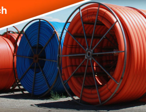
HORIZONTAL DIRECTIONAL DRILLING
Horizontal Directional Drilling (HDD) allows conduit to be installed with out any interruptions under
highways, water, rural areas, etc. conduit such as fiber, sewer, water and electric can be installed. There
are three stages to HDD.
PILOT HOLE
The construction crew begins the preplans of the bore path to carefully avoid any underground
constructions, such as underground utilities. Once the bore path is cleared, the directional bit enters the
entrance pit. Which the entrance pit is used to contain and manage the drilling fluids (drilling mud).
During the whole process the crew are in radio communication with each other. The drill bit is tracked
by a radio detection device. This always the crew to detect the dept of the bit and give information on
where to steer.
REAMER
Once the drill bit makes it though the exit point, a reamer is then placed on the end of the bit to enlarge
the pilot bore. The bore path is typically engaged by one and half size of the conduit that is being
installed.
INSTALLING THE PIPE
The conduit is simply pulled in place by the drill bit. During this time, the crew is recording the axial
tension force readings, constant insertion velocity, mud flow circulations/exit rates and footage length
that is being installed.
ITEMS TO MONITOR
- Pilot Hole
- Axial Tensile
- Mud Flow
- Pullback Pressure
PILOT HOLE
During a directional drilling project, pilot hole reaming is a key factor for it to be successful. The drilling
of the pilot hole establishes the pathway of the drill rod and the location of the pipe. The bore head
then can be tracked electronically as a guide. During the design of the drill rod pathway, a key
consideration is creating as large of a radius of curvature as possible within the limits of the right-of-way
which minimizes curvature. The curvature induces bending stressed and increases the pullback load.
This is due to the increase in frictional drag when pulling the pipe around a curve due to a component of
the pulling force acting normal to the curvature, which is known as the capstan effect. When having a
higher tensile stress, it reduces the pipe’s collapse resistance.
AXIAL TENSION
With the complex interaction between the pipe and soil, considerable judgement is required to predict
the pullback forces. Axial tensile force during pullback is subjected to the pipe. This is caused by the
following:
- Frictional drag between the pipe and borehole or slurry
- Frictional drag on the ground surface
- Capstan effect around drill-path bends
- Hydrokinetic drag
DRILLING MUD
When boring, fluid bentonite or clay additive (drilling mud) is injected into the bore. This stabilizes the
hole and removes soil cuttings. Drilling mud occurs during cutting and reaming, which can be made of
clay or polymers. However, the primary clay is sodium montmorillonite (bentonite) for drilling mud. To
produce mud, bentonite (that is properly ground and refined) is added with water. To keep the pipe and
borehole lubricated during pullback, the fluid must have sufficient gel strength. The loss of lubrication
could cause a locking up and overstressing of the pipe during pullback.
PULLBACK
Pullback involves pulling the entire length of the pipe in one segment back through the drilling mud
along the reamed-hole pathway. Pullback speed ranges between 1 to 2 feet per minute.
Proper procedures that need to be followed.
- Pipe handling
- Cradling
- Bending minimization
- Surface inspection
Procedures that should be recorded.
- Axial tension force readings
- Constant insertion velocity
- Mud flow circulation/exit rates
- Footage length installed
PULLBACK FORCE
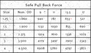
The pulling force which overcomes the combined frictional drag, capstan effort, and hydrokinetic drag, is
applied to the pull-head and first joint of HDPE pipe. The axial tensile stress grows intensity over the
length of the pull. It is recommended DR 11 or thicker is used for directional boring. The tensile stress in
the pipe wall due to pullback force (787) for DR 11, cannot exceed the permitted tensile stress of the
pipe material. It can cause breakage or stretching of the pipe if exceed. Increasing the pipe wall
thickness will allow for a great total pull-force.
FRICTIONAL DRAG RESISTANCE
Frictional force can create the pipe to resist during pullback, which can cause the pipe to stretch or
break. This is can be created by the following.
- The fictional drag between the pipe and drilling slurry.
- The pipe between and the borehole.
- The pipe between and the entry area.
- The capstan effect at bends.
- The weight of the pipe.
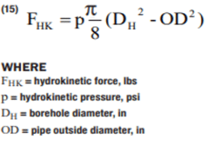
HYDROKINETIC DRAG
During the drilling process, movement in the pipe is resisted by the drag force of the drilling fluid
“slurry.” The hydrokinetic pressure ranges between 4 to 8 psi.
TENSILE STRESS DURING PULLBACK
During pullback, the Nom. OD fiber tensile stress should not exceed the safe pull stress. It is advisable to
monitor the pulling force. Making sure to use a pipe of higher DR mechanical breakaway connector to
prevent over-stressing the pipe. To obtain the Nom. OD fiber tensile stress, use the following formula:
TENSILE STRESS IN THE PIPE DUE TO THE PULL BACK FORCE + HYDROKINETIC PULLING FORCE + TENSILE
BENDING STRESS DUE TO PIPE CURVATURE = NOM. OD FIBER TENSILE STRESS
